ME 350: Disc Sorting Device

As part of Design and Manufacturing II (Winter 2022), myself and a team of 4 other students designed, built, and tested a four-bar linkage to sort colored discs. Our design broke the course record for the project, successfully sorting 18 discs in 13 seconds. At the conclusion of the semester, we presented our device at the U-M Mechanical Engineering Undergraduate Symposium

Robotics project setup with motor and circuit board, featuring wires and gears on a wooden table.

The Problem

Summary: Design a four-bar linkage that sorts colored discs onto the corresponding colored zones (regular or bonus) of the provided playing field.

Scoring: Points are awarded based on the accuracy of placement within zones. Speed is taken into account — devices capable of sorting 18 randomly ordered discs faster than 90 seconds gain extra points.

Constraints: Each team is provided a kit of linkage parts, which must be used. Custom parts may be machined, but these parts cannot be used in the construction of any of the four links. No part of the mechanism is allowed to touch the Sorting Area, only the Setup Area.

Diagram of a playing field with labeled zones: Red Zone, Yellow Zone, Blue Zone, and their respective Bonus Zones. Each zone has two concentric circles labeled with point values. Additional labels include "Playing Field," "Sorting Area," and "Setup Area." The University of Michigan Mechanical Engineering logo is present.

Design and Simulation

Diagram of a mechanical assembly with labeled components, including an extended length coupler link, input link, motor, electromagnet, custom mounting bracket, and disc feeder; displayed on a surface with colored circles.
Series of four images labeled (a) to (d) showing a mechanical device with gears and an arm, interacting with colorful circles on a surface. The device and arm positions vary slightly in each image.
Four graphs depicting power consumption, angular velocity, angle, and torque versus time. Graph (a) shows power consumption; graph (b) displays angular velocity; graph (c) presents angle; graph (d) illustrates torque, all over a time range of 0 to 0.45 seconds.

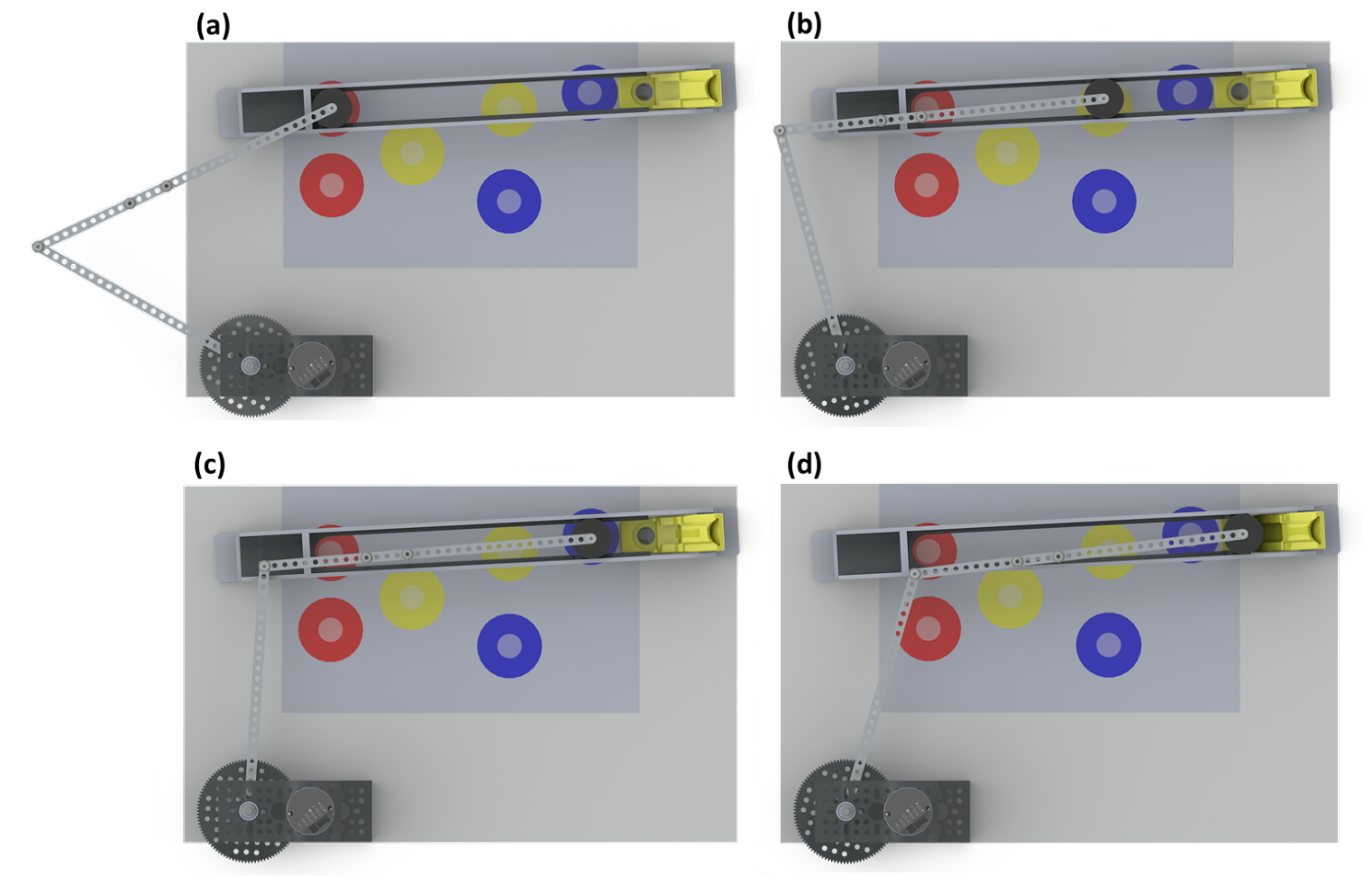
To hit all three bonus zones and maximize points, I designed a slider-crank four-bar linkage mechanism. This mechanism uses an electromagnet as its slider link — this component is also utilized for picking up and dropping discs.

The custom mounting bracket serves two purposes: constraining the electromagnet to slide over the desired zones and supporting the weight of the links as they cross over the Sorting Area.

The image to the right shows a SolidWorks render of our proposed initial design.

To ensure our crank slider would not reach a toggle point, the maximum desired transmission angle is 45°. Using SolidWorks, we determined our design had a maximum transmission angle of 33.88°.

Using ADAMS, we simulated the motion of our mechanism, measuring linkage power (Fig. a), angular velocity (Fig. b), angle (Fig. c), and input link torque (Fig. d).

Prototyping and Machining

Technical drawing of a component labeled 'Slotted Foot' with dimensions and views. Includes front, side, and isometric views, detailing measurements in inches. Features include holes and rounded corners. Material specified as aluminum. Document includes notes and revision information from ME 350 Team 41.
Technical drawing of a mechanical part labeled "FOOT," featuring dimensions and details such as M7x1 threaded holes, radii, and material specifications in aluminum. Presented by ME 350 Team 41, it includes multiple views and measurements for manufacturing.
Technical drawing of a slide rail with dimensions, material specifications, and assembly instructions. Annotated with measurements in inches, detailing the design of the slide rail, including side view, section view, and top view. Notes section includes specifications like material (aluminum), finish (burr free), and tolerances.
A hand holding a blue slider over a diagram with red, yellow, and blue zones labeled with point values on a grid. The diagram is marked with 'Playing Field' and 'Setup Area' labels, and has a logo of a university's mechanical engineering department.
Two machined metal brackets with threaded holes on a wooden surface.
Metallic rectangular frame with bolts, placed on a textured metal surface.

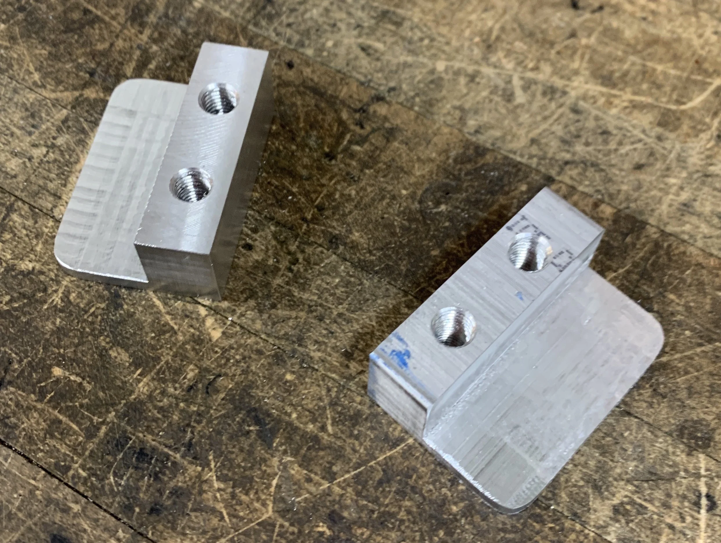
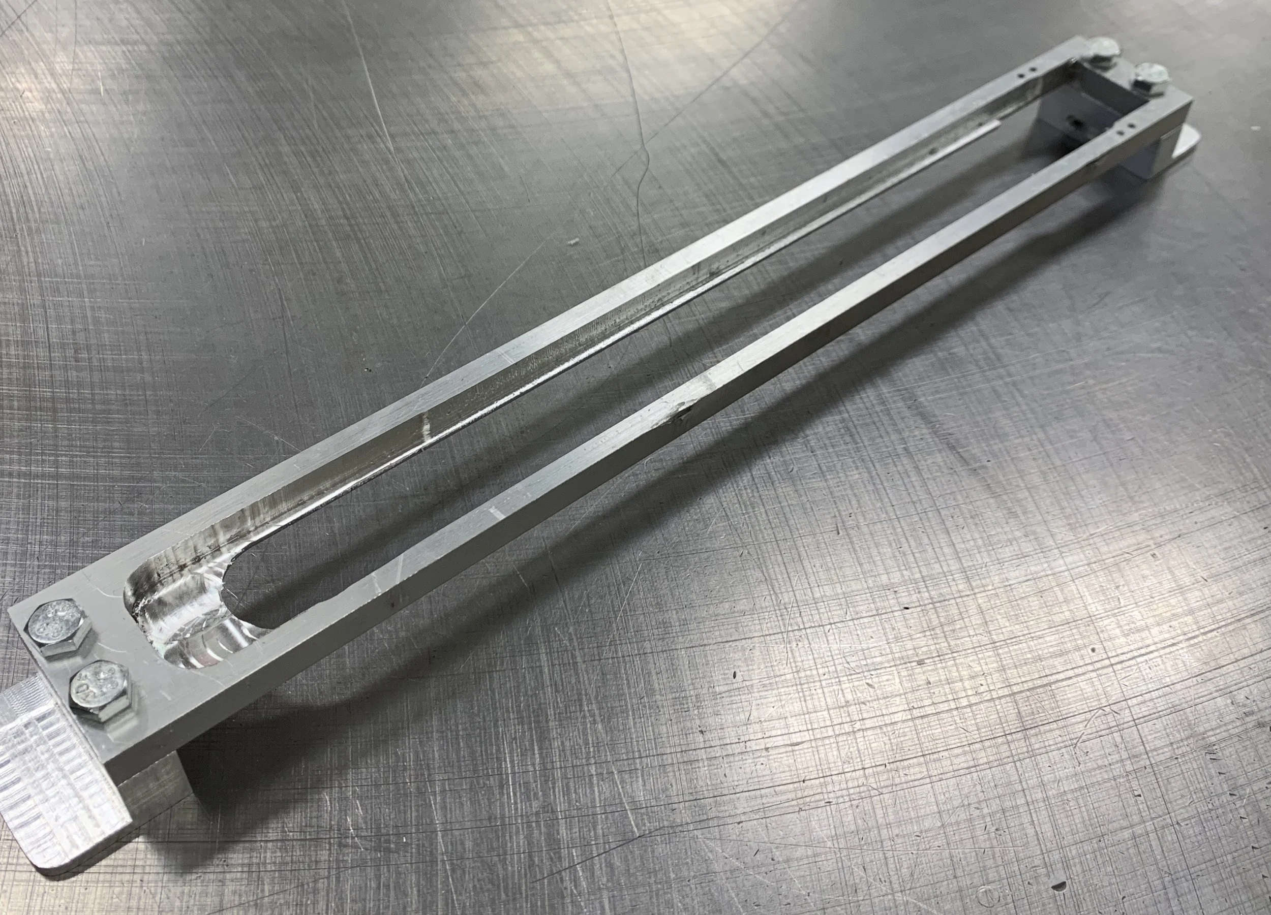
Our custom slide rail was prototyped using a Prusa MK2 FDM 3D Printer (left), then redesigned for conventional machining (right) and handmade on a mill (below).

Electronics and Control

Diagram of an Arduino UNO project including a breadboard, 255-6141-ND limit switch, EG1903-ND toggle switch, 10kΩ resistor, 5202-0002 motor/encoder, L298N H-Bridge, R-1207-12 electromagnet, TCS3200 color sensor, all connected to a SoulBay multi-voltage power supply.
Flowchart illustrating a four-state process: State 1 is Calibration, ensuring encoder count zero; State 2 involves picking up a disc using motor voltage to a specific location; State 3 determines disc color using a sensor and adjusts position; State 4 moves to a specific zone. A PID Controller diagram shows continuous background operation of proportional, integral, and derivative functions controlling a plant system, indicated by equations and feedback loops.

To actuate our linkage, we used a DC motor and encoder, controlled using an Arduino Uno and H-bridge. A color sensor was placed inside our disc feeder to determine which disc was being picked up, and an electromagnet transported the disc to its destination.

A PID controller was implemented and visually tuned using the Ziegler-Nichols method to accurately drop discs.