ME 218A: Ed’s RV Ed-Splorer

As part of Smart Product Design (ME 218A, Fall 2023), myself and a team of 2 other students designed and built a mechatronic spotlight game. The project was completed from start to finish in 3 weeks, and was presented at the 2023 ME 218A showcase at the conclusion of the quarter.
Hardware Design
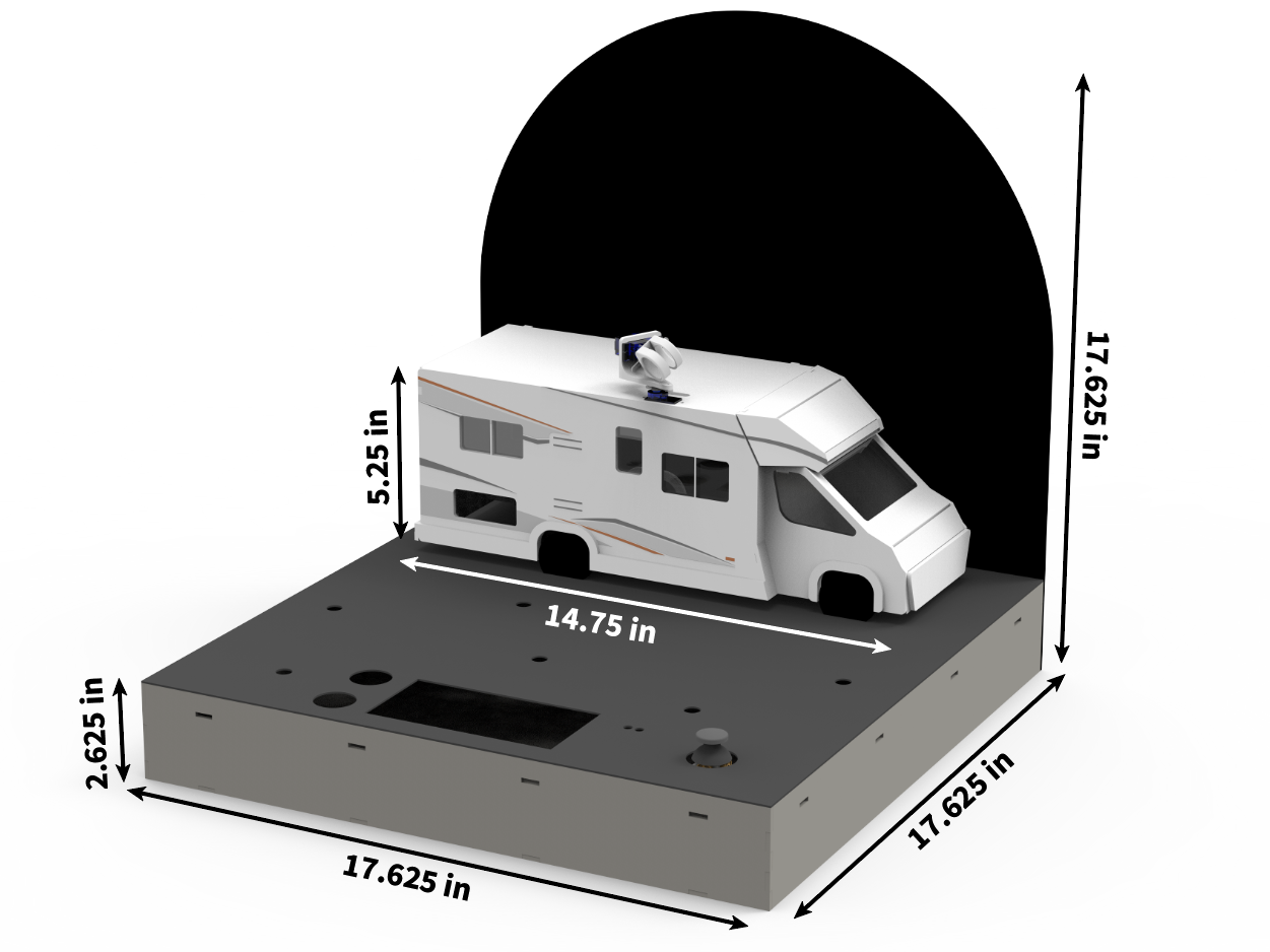
Summary: Design a four-bar linkage that sorts colored discs onto the corresponding colored zones (regular or bonus) of the provided playing field.
Scoring: Points are awarded based on the accuracy of placement within zones. Speed is taken into account — devices capable of sorting 18 randomly ordered discs faster than 90 seconds gain extra points.
Constraints: Each team is provided a kit of linkage parts, which must be used. Custom parts may be machined, but these parts cannot be used in the construction of any of the four links. No part of the mechanism is allowed to touch the Sorting Area, only the Setup Area.


Software Design

To ensure our crank slider would not reach a toggle point, the maximum desired transmission angle is 45°. Using SolidWorks, we determined our design had a maximum transmission angle of 33.88°.

Two main state machines were used to achieve functionality.
To ensure our crank slider would not reach a toggle point, the maximum desired transmission angle is 45°. Using SolidWorks, we determined our design had a maximum transmission angle of 33.88°.
Circuit Design
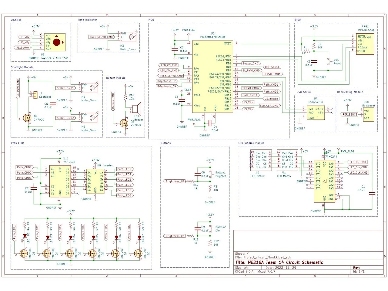
To actuate our linkage, we used a DC motor and encoder, controlled using an Arduino Uno and H-bridge. A color sensor was placed inside our disc feeder to determine which disc was being picked up, and an electromagnet transported the disc to its destination.